 We will learn to control an electric relay using Arduino
Components needed:
| ITEM | PRICE |
|---|---|
| Arduino Uno or Mega | ~$15.00 |
| Wires and breadboard | $10.00 |
| 1 Channel Relay | $4.00 |
| Piezo Buzzer (optional) | $2 |
| Outlet Housing | $1.00 |
| Face Plate | $3.00 |
| Receptacle | $5.00 |
| Power cable | $10.00 |
Electric relay is the key player in this project because it will, eventually, turn on/off the water pump to water plants. Relays are used when one electric circuit needs to control another. In our case, the 5V low-power Arduino electric circuit controls the 110V electric circuit of the outlet.
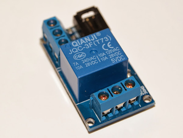
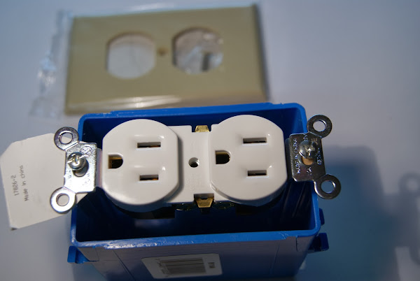
I would encourage you to build this sample project to make sure that your relay works before you start assembling all of the pieces together. Many relays use electromagnetism to open or close an external electric circuit mechanically, making a distinct sound when the relay switches its state. Even if you don’t have the LED elements required for this sample project, you will still be able to hear how the relay switches its state. To learn more about how different types of relays function, see Wiki. Other components are not as sophisticated: Faceplate, Receptacle & Housing
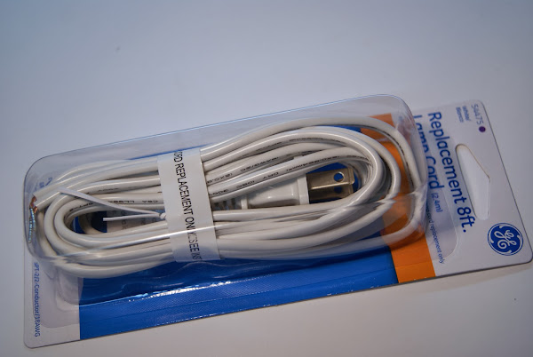
Power cable
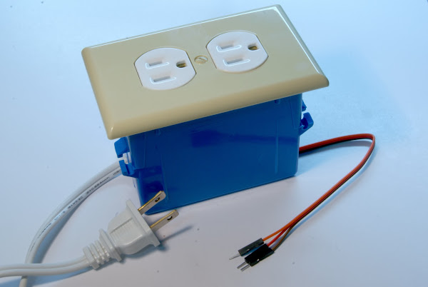
I inserted the power cord through the holes in the the housing and connected one power cord wire to the receptacle through the relay, and another wire directly to the receptacle.
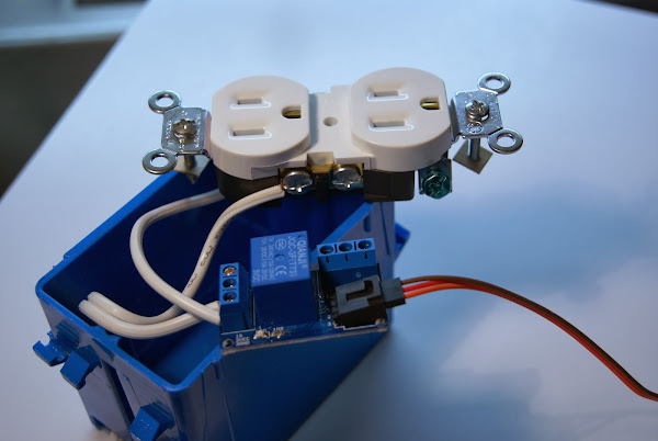
After I hid all the components inside the housing, and screwed the faceplate, the result looked like this:
The electric plug goes into your power network, and the relay wires connect to the Arduino board. To make the demo more impressive, I used the Imperial March code code. It requires a piezo buzzer to be connected to the pin 11. The code makes uses built in Arduino LED, connected to the pin 13 to visualize the beats. If we connect signal pin to the Arduino’s pin 13, whatever device we connect to the outlet (a lamp in my case) will turn on and off to the beats of the Imperial March. Cool, right? :) Here is how the pins are connected:
| ARDUINO PIN | COMPONENT PIN |
|---|---|
| 13 (Digital Out) | Relay Signal Pin |
| 11 (PWM) | Buzzer Signal Pin |
| 5V | Relay VCC Pin |
| 3.3V | Buzzer VCC Pin |
| GND | Relay Ground Pin |
| GND | Buzzer Ground Pin |